Most ultrasonic transmitters and receivers are built around timer IC 555 or complementary metal-oxide semiconductor (CMOS) devices. These devices are preset-controlled variable oscillators. The preset value of the working frequency is likely to drift due to mechanical vibrations or variations in temperature. This drift in frequency affects the range of transmission from the ultrasonic transducer.
The ultrasonic transmitter and receiver circuits described here use CD4017 decade counter ICs.
The transmitter circuit (Fig.1) is built around two CD4017 decade counter ICs (IC1 and IC2), D-type flip-flop IC CD4013 (IC3) and a few discrete components. The arrangement generates stable 40kHz signals, which are transmitted by transducer TX.

The crystal-controlled radio-frequency (RF) oscillator built around transistor T 1 (BC549) generates an 8MHz signal, which serves as input to the first decade counter built around IC1. The decade counter divides the oscillator frequency to 800 kHz. The output of IC1 is fed to the second CD4017 decade counter (IC2), which further divides the frequency to 80 kHz.
The flip-flop (IC3) divides 80kHz signal by 2 to give 40kHz signal, which is transmitted by ultrasonic transducer TX.
Coil L is made with 36SWG enamelled copper wire that is wound 15 times around an 8mm-diameter plastic former as used for radio oscillators, which has a ferrite bead.
The transmitter circuit works off 9-12V DC.
The receiver circuit (Fig.2) is built around a single decade counter CD4017 (IC4) and a few discrete components. To check the working of the transmitter, it is necessary to down-convert the 40kHz signal into 4kHz to bring it in the audible range. By using the receiver, the 40kHz ultrasonic transmitter can be tested quickly. The receiver’s transducer unit (RX) is kept near the ultrasonic transmitter under test. It detects the transmitted 40kHz signal, which is amplified by the amplifier built around transistor BC549 (T2). The amplified signal is fed to decade counter IC4, which divides the frequency to 4 kHz. Transistor T3 (SL100) amplifies the 4kHz signal to drive the speaker.
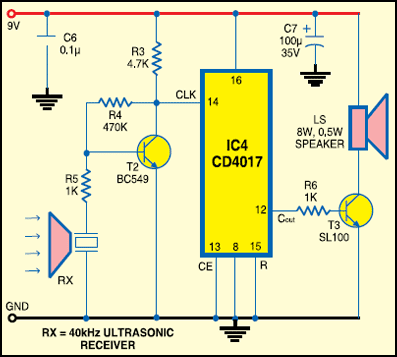
Use a 9V PP3 battery to power the receiver circuit.
House the transmitter and receiver circuits in separate small cabinets. If the 40kHz transducer under test is working, the receiver circuit produces audible whistling sound.

